Verification according to SIA 264
Check for shear
The shear design resistance shall be conservatively determined as the resistance of the steel section in accordance with SIA 263.
Check for compression:
The design plastic resistance to normal force of steel-concrete cross-section:
![]()
where: | Aa | - | area of steel cross-section |
Ac | - | area of concrete | |
fy | - | steel yield stress | |
fck | - | compressive strength of concrete | |
γa | - | partial factor for resistance of of steel = 1.05 |
γc | - | partial factor for resistance of concrete = 1.5 |
Utilization ratio:
![]()
where: | N | - | design axial force |
Mpl,Rd | - | The design plastic resistance for bending |
Check for bending:
The design plastic resistance of the steel-concrete section is determined from the interaction diagram.
Mpl,N,Rd is the bending capacity allowing for the compressive force.
It is assumed that concrete does not act in tension, there is a plastic stress distribution on steel and concrete.
A reduced strength value of 0.85 fcd is assumed for the concrete part outside the steel section, full strength is assumed for the concrete inside the steel section fcd, where fcd = fck / γc.
In case of the big shear, i.e. if Q / VRd > 0.5, a reduced yield strength given by fyW = fy [1 - (Q / VRd)2] is considered on the parts of the steel cross-section that transfer the shear.
Utilization ratio:
![]()
For steel with a yield strength greater than 400 MPa, a limit of 0.8 is used.
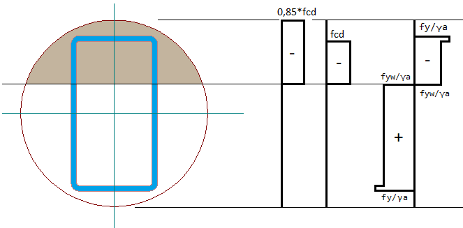
Diagram for determining the design plastic resistance for bending Mpl,N,Rd.